- RUNAROUND :A NOVEL by C.Sasha Pop!
- What is Kobo Super Points??
- Old Creole Days.
- Join Kobo & start eReading today;
- Reward Yourself.
- Generation V.
The frequency at which flicker noise is equal to thermal noise is called corner frequency of flicker noise. Substituting in the above equation and solving for , we get. From Eq- 6 , flicker noise is directly proportional to. With technology scaling increases, thus flicker noise also. Though flicker noise is small at RF frequencies, its effect is considerable in mixers and oscillators due to nonlinearity or time variance of those circuits.
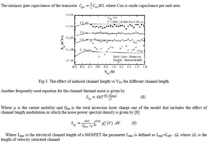
The fluctuations in the channel charge in the inversion region will induce a noisy current in the gate due to capacitive coupling. According to Van der Ziel, a gate circuit model that represents gate induced noise is illustrated in Figure 1. Thevenin equivalent circuit representation of gate induced noise shown in Figure 2 is obtained through parallel to series impedance transformation. The above two circuits are interchangeable under the condition, or. The spectral density of gate induced noise is proportional to , and hence the gate induced thermal noise is not a white noise source.
A RFIC designer's notes
Gate induced noise is partially correlated with the drain noise, with a complex correlation coefficient given by. Using the correlation coefficient, the gate noise can be expressed in terms of correlated and uncorrelated components as,. Furthermore the transconductances alter their controlling nodes, i. The current equations of the two parasitic diodes at the bulk node and their derivatives write as follows.
Some of the electrical parameters can be derived from the geometry and physical parameters. The oxide capacitance per square meter of the channel area can be computed as. The transconductance coefficient can be calculated using. The surface potential is given by with temperature voltage.
A Review of Analytical Modelling Of Thermal Noise in MOSFET
The bulk threshold also sometimes called the body effect coefficient is. And finally the zero-bias threshold voltage writes as follows. Whereas denotes the flat band voltage consisting of the work function difference between the gate and substrate material and an additional potential due to the oxide surface charge.

The temperature dependent bandgap potential of silicon substrate material Si writes as follows. With the bandgap is approximately. The work function difference gets computed dependent on the gate conductor material.
Noise in MOS Transistors
This can be either alumina , n-polysilicon or p-polysilicon. The work function of a semiconductor, which is the energy difference between the vacuum level and the Fermi level see fig. The abbreviations denote electron affinity of alumina electron affinity of silicon vacuum level conduction band valence band Fermi level intrinsic Fermi level bandgap of silicon at room temperature Please note that the potential is positive in p-MOS and negative in n-MOS as the following equation reveals.
When the gate conductor material is a heavily doped polycrystalline silicon also called polysilicon then the model assumes that the Fermi level of this semiconductor is the same as the conduction band for n-poly or the valence band for p-poly. In alumina the Fermi level, valence and conduction band all equal the electron affinity. If the zero-bias bulk junction bottom capacitance per square meter of junction area is not given it can be computed as follows.
That's it for the physical parameters.
A Review of Analytical Modelling Of Thermal Noise in MOSFET | Open Access Journals
The geometry parameters account for the electrical parameters per length, area or volume. Thus the MOS model is scalable. The diffusion resistances at drain and gate are computed as follows. The sheet resistance refers to the thickness of the diffusion area.
If the bulk junction saturation current per square meter of the junction area and the drain and source areas are given the according saturation currents are calculated with the following equations.
